If i get this part wrong the rest of the engine has no chance of working.
The Top Plate can be seen in the image below, its the eh..... plate on the top :)
As you can see in the image below it also has 2 two millimetre thick pieces of plastic that screw into it, these are for the A Frame to slot into.
So the Top Plate needs 10 micro millimetre precise holes milled through it and one large hole for the power cylinder.
So lets go :).
First the holes for all the screws and the single hole for the power cylinder have to be made.
This is the AutoCAD file that i created , i have the points where the CNC machine will mill highlighted in blue so they can be seen, they are only single points in AutoCAD and would not be seen otherwise.
The CAD file is then converted to a dxf (drawing exchange file) and sent to LazyCAM. In LazyCAM i set the depth that i would like the CNC machine to go through the aluminium, the speed at which i would like it to cut, the direction of cut and also the order in which i would like it to do things, all these things can be changed.
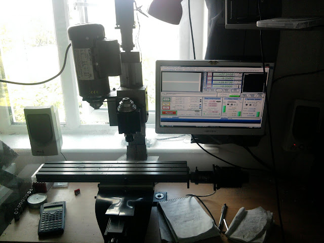
Once i am happy with the Cam file, i ask LazyCAM to create the GCODE for all of the parameters that i have set above. When that is done i open Mach 3 and load the file that LazyCAM has just created, here it is shown in the screen below.
If everything looks good there i hit the "Cycle Start" button and Mach 3 takes control of the CNC machine.
Once the holes have been drilled the top plate needs to be cut away from the aluminium sheet that it is made of, this is just a circular cut that will be done in the same fashion as above - circle drawn in AutoCAD, file sent to lazyCAM, file sent to Mach 3 and then the CNC machine cuts the circular profile.
And here is the final product after cutting, i'm pretty happy with it (apologies for the picture quality, i need a new camera) -
In the next post i'll show a video of the machine cutting the displacer, get the ear muffs ready, its pretty loud :)


